Pick & place driven by a CAD file
We build a system that recognizes parts on a production line straight from STL/CAD files and tells the robot what to grasp and how. The system learns each new part automatically from its file, and station changeover takes a few minutes.
contact: kontakt@dudarobotics.pl
From an STL file to a grasp — five steps
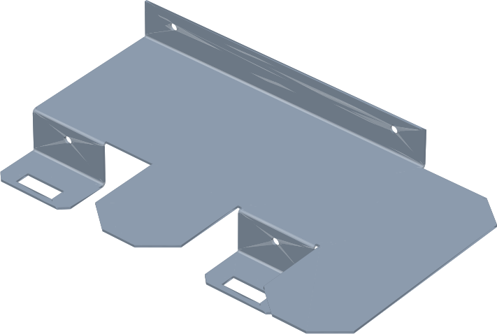
The same CAD model you already have from design or from your customer is enough for the station to start working with a new part.
STL / CAD file
You upload the part model — no photo sessions, no data collection.
Part profile
The system learns the part from CAD automatically: recognition model, grasp point and a validation report.
3D camera
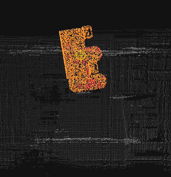
A point cloud of the scene — conveyor, table or bin.
6D pose engine
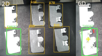
AI recognition in the image, pose from PnP, refined with ICP on the point cloud — with a confidence score.
Robot picks
Pose and grasp point go to the robot — pick and place.
Two ways to work with us
Automated part picking
- Picking parts off the conveyor after bending, stamping, casting or machining
- Sorting mixed parts against their CAD references
- Machine loading and short-run packing
- Viable even at hundreds of pieces and frequent changeovers
A 3D vision engine for your cells
- A container with an API / ROS2: point cloud in → 6D pose + grasp point out
- Part profiles prepared automatically from your client’s STL files
- Flexible per-station or per-project licensing — the margin stays with you
- Engineering support straight from the makers
Geometry over appearance
Works on difficult parts
Smooth, metallic, bent, textureless surfaces — exactly where classic vision systems fail. Recognition trained on CAD-generated data plus a 6D pose computed on the image and point cloud (PnP + ICP) handle what the image alone cannot.
It teaches itself — from CAD
The system generates its own training data from the CAD model and trains the recognition network — no photo sessions, no manual labeling. Preparation runs offline, and switching the station to another part takes a few minutes.
Measured, not promised
Every part goes through accuracy validation (an ADD-S report) before it reaches the station. You know what to expect before you invest.
Open architecture
Any 3D camera and any robot controlled over ROS2. A part library in the cloud or on-premise, with full data isolation for every client.
Start with four low-risk steps
Feasibility check
You send STL files and photos of your parts — we assess the fit and point to the best first operation.
free of chargeProof of concept
Your parts on our test rig, with an accuracy report and a recording of the system at work.
Pilot on your line
A cobot-and-3D-camera station on a chosen operation, with clear success criteria.
Scale-up
New parts and operations are just new STL files — no station rebuild.
We play with our cards on the table: the technology is implemented and tested on our test rig, and we deliver the first deployments as partner pilots — on preferential terms, with clear go/no-go criteria after every stage.
Frequently asked questions
What is CAD-driven pick & place?
It is a 3D vision system that recognizes parts on a production line based on their STL/CAD model and gives the robot a 6D pose and a grasp point. Recognition combines AI on the image with PnP + ICP matching on the 3D camera point cloud.
Do I need photo sessions or manual data labeling?
No. The system generates training data from the CAD model (synthetic data) and learns each part automatically, offline — no photo sessions and no manual labeling.
How long does changeover to another part take?
A few minutes for a part that has been prepared before. Preparing a new part happens automatically from the STL file and requires no vision engineer.
Which cameras and robots does the system work with?
Any 3D camera that outputs a point cloud and any robot controlled over ROS2. The part library can run in the cloud or on-premise, with data isolation for every client.
Which parts fit the system best?
Rigid parts with defined CAD geometry: bent sheet metal, castings, stampings and CNC-machined parts — including shiny, metallic and textureless parts that defeat classic vision.
How do I start working with DudaRobotics?
With a free feasibility check: send 1–2 STL files and a few photos of your parts to kontakt@dudarobotics.pl. We usually reply within 48 hours and are happy to sign an NDA.
Let’s test your parts
Send 1–2 STL files and a few photos of parts from your production. We’ll come back with a feasibility assessment and a proposed next step. We usually reply within 48 hours, and we’re happy to sign an NDA.
kontakt@dudarobotics.pl